The design without fuses is not typically usedfor system voltages lower than about 345 kV. Capacitor banks indicate that pre-insertion resistors can significantly reduce transients.

Capacitor Bank Design Download Scientific Diagram
Leaking from Capacitor Units.

. The cause is that there shall be more than 10 elements connected in series so that the. Research has been conducted on low-inductance high-voltage capacitor banks that can supply huge pulses of current for many pulsed-power applications. Bank ratings of MV HV capacitor systems for industrial applications Medium And High Voltage Capacitor Systems For Industrial Applications Ratings dimensions and other details shall be made available on request 6 Figure - 5 3000kVAr 132kV 3 Phase 50Hz Metal Enclosed Double Star Connected MV Capacitor Bank With Neutral Current Transformer.
Back-to-back capacitor banks A capacitor bank energized in close proximity to a previously energized capacitor bank results in generating a high-frequency inrush currents. Highly compatible for different IPL elight machines Details. All high voltage capacitor bank design wholesalers high voltage capacitor bank design manufacturers come from members.
Capacitor banks with a high energy density more than 1 Jcm3 and modern semiconductor switches can be used to create compact energy amounting to several hundreds of kilo-Joules kJ and generating high. The capacitor bank in delta connection can be utilized for high voltage however it is not achievable sometimes as in delta connection. The bank design requires the use of eight units per phase and 24 total units which results in rated unit kvar of 1800036750 kvar.
High voltage capacitor bank design. 13 eg magnetized tar- get fusion MTF Z. Vishay Intertechnology Inc its affiliates agents and employees and all persons acting on its or their behalf.
The EMRG utilizes an injector a high voltage power supply a capacitor bank inductors and rails. First is 3 phase single star connected which is suitable where voltage is preferably low say up to 66 kV. Each phase consists of.
The capacitor bank in serviceremains nevertheless consecutive break downs of elements will cause removal of the bank. The capacitor banks consist of either single-phase or three-phase capacitor units suitably designed and connected in order to meet the total amount of reactive power required at the specified frequency and voltage. Capacitor Bank Design As Ive mentioned previously the main purpose of a capacitor bank for the purposes of high power experiments is to deliver as much power as possible as quickly as possible and in order to do that the capacitors have to be able to deliver very large currents.
Flexible VAR control the substation capacitor bank configuration may consist of up to 6 separately switched capacitor stacks. The system can be designed as a fixed or switched capacitor bank. Description High voltage AC capacitor banks indoor outdoor Type High voltage AC 3-phase capacitor banks Technology All-film polypropylene aluminum foil Voltage min.
The aim of project called Reactive power compensation panel was to design capacitor bank with rated power of 200kVar and rated voltage of 400V adapted for operation with mains where higher order harmonics are present. High Energy density 6. Low EMI radiation 7.
Eq eq pk LL L C I u V u u 3 2 x 1000 eq t L C f 2Su u 1000 C eq is the equivalent capacitance of the two capacitor banks in series in farads. Four fuseless strings with two series-connected units per fuseless string. This paper presents an overview of capacitor switching options and the results of computer.
200-400VDC 200 -450VDC Capacitor bank. Handling and disposal of capacitor insulating fluid should comply with state federal and local regulations. The voltage level is monitored and used to switch in and out three-phase capacitor stacks as required for correct VAR compensation so the bus.
Other is 3 phase double star connected bank assembled with minimum 6 Nos of single phase units preferably for systems where voltage is higher say 11 kV and above. Single wye option. A High-Voltage Capacitor Bank Design with a Built-in Spark Gap Switch.
Buy High Voltage Capacitor Bank on ebay. When handling the leaking fluid avoid contact with the skin and take measures to prevent entry into sensitive areas such as eyes. The entire substation bank is typically switched with a circuit breaker.
220V110V AC 50-60Hz Output. The capacitor bank was to be power capacitor based with automatic control by power factor regulator. Ad Free Shipping Available.
High voltage protection 3. We doesnt provide high voltage capacitor bank design products or service please contact them directly and verify their companies info carefully. Approved for public release.
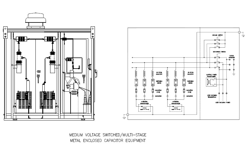
Another mode of failure in the capacitor bank is leaking due to the failure of the cans. This article describes an approach that provides such a balance in the context of mobile outdoor enclosed capacitor banks for medium voltage networks. Designing medium voltage capacitor banks balances the potentially conflicting requirements of minimised cost long life infrequent mainte-nance ease of operation and fitness for purpose.
In MV installations capacitor banks may be installed either outdoors surrounded by a fence or in the pole of a MV overhead line or indoors in metallic enclosures switchgears. 2 increment in the voltage. HV capacitor banks are installed outdoors surrounded by a fence and LV capacitor banks are installed indoors in metallic enclosures switchboards.
RELIABILITY FUNCTION OR DESIGN OR OTHERWISE. By Paul R Berning and Peter T Bartkowski. The complete phase voltage is given across every capacitor while in star type connection it is lesser as compared to.
The ability to incorporate another circuit parameter the pre-insertion resistor provides opportunities for improved high-voltage capacitor bank design. There are two types of banks depending upon the mode of connection. The injector fires 2300 psig Nitrogen gas into the system to provide an initial velocity.
High-energy capacitor banks are designed to generate very high currents and ultimately v ery high magnetic fields for various applications.
Medium Voltage Capacitor Banks Multi Step Controllix
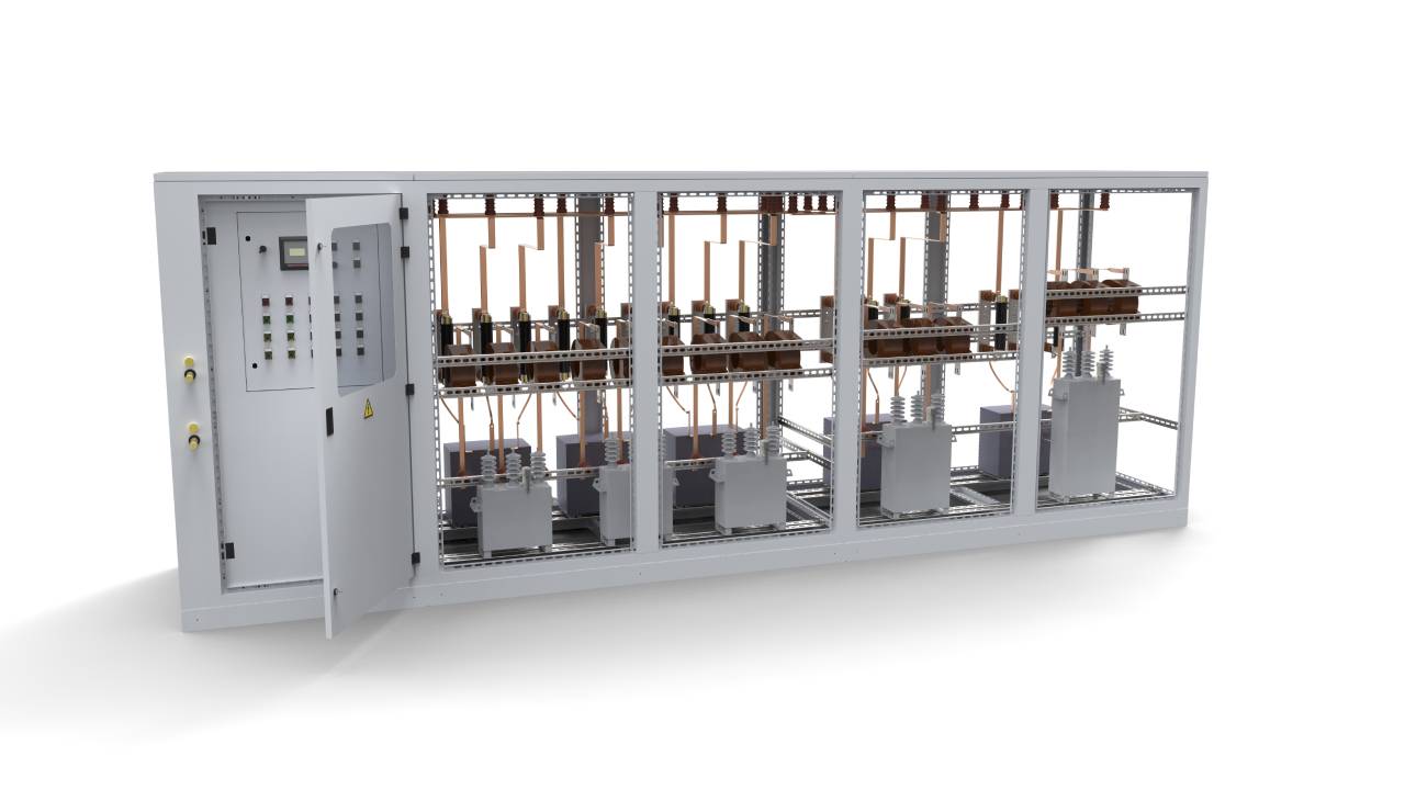
Enclosed Type High Voltage Capacitor Banks Panel Mounted Series Abps System

A Diagram Of The High Voltage Circuits The Inductive Load Capacitors Download Scientific Diagram
Externally Fused Shunt Capacitor Bank And Capacitor Unit Download Scientific Diagram

Capacitor Bank Design Download Scientific Diagram

High Voltage Capacitor Ge Grid Solutions Film Pole Mounted Power

Step By Step Tutorial For Building Capacitor Bank And Reactive Power Compensation Panel Eep
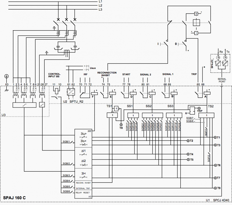
The Basics Of Capacitor Banks Protection Eep
0 comments
Post a Comment